
There's a lot that goes into making a nice crystal radio set, so this is going to have to be broken down into two parts. The first part is the actual making of a functional radio, and the second part is making the whole arrangement look nice. In this part, I'm actually going to tell you more than just how to make a crystal radio, but I'm also going to explain how and why they work.
Crystal radios are pretty Steampunk in and of themselves, since they were first developed in the late 19th century. The technology was discovered in 1874, though it wasn't put into commercial use until the very early 20th century. The great thing about a crystal radio is that it doesn't need a separate power source, since all the power it needs is picked up from the antenna. As a result, most simple sets are pretty low-volume, but they still work just fine!
Overview
For those of you who aren't tech-savvy, this project is really, really easy. Anyone can do it, provided that you have the right parts. Here are all the parts you need to make a crystal radio, and I'll explain what they are, how they work, and where to get them:
You may notice that there are only four parts. Yeah, that's really all you need!
Before I get into explaining what they are and what purpose they serve, let me tell you a little bit about how the whole arrangement works.
With a crystal set, it's important to have an antenna. Your coil (which I'll be talking about later) can function as sort of an ad-hoc antenna, but for the best results, you need a good antenna. The reason you need a good antenna is because the more antenna you have, the more power your set will receive, and the louder it will be.
That's because radio waves are, for all intents and purposes, wireless power. Yes, the invisible waves that constantly surround and penetrate you are strong enough to power a simple radio.
How Is That Possible?
Some of you may be familiar with Nikola Tesla's experiments in providing the world with wireless power. Well, "power" can mean a lot of different things. We often think of electricity as water, flowing out of our electrical sockets as needed. In reality, it's a lot more complicated than that, and like water, electricity has waves, currents, and other characteristics that govern its various attributes.
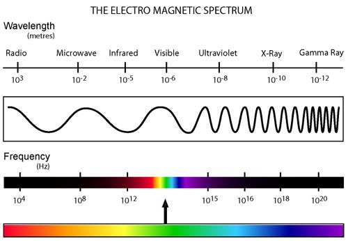
While you may think of radio waves and electricity as being different, they're actually the same phenomenon! Radio waves are just fluctuations in the electromagnetic fields that surround us at all times. Think of the waves in the ocean: they can push you around because each wave has its own kinetic force. Well, you can kind of think of radio waves like invisible ocean waves. They're invisible to us, because they don't react with us. However, a copper wire can "see" the waves because it's a conductor of electricity!
You can essentially think of the waves as vibrations. When they hit a conductor, they make the conductor vibrate. In this case, the vibrations are so small that they're almost impossible to hear. That's why you need a crystal (or diode) to adjust the signal, and then a very, very sensitive earpiece to hear it. When you use a powered radio, it adds that power to the circuit, amplifying the vibrations until they become quite loud. That's what the battery (or plug) does. No matter what kind of radio you have, it's always picking up the radio waves, even when the power is off. You just can't hear them unless you're amplifying the circuit because of the way modern radios are built.
Now that you have a general idea of the principle behind a crystal radio, let's look more specifically at the parts and how they work.
The Wire
Not to be confused with the television show of the same name, the wire is the skeleton of your radio. Your wire is going to serve two purposes:
- It will "catch" the radio waves
- It will allow you to tune the radio
The radio wave catcher is known as your antenna, and the tuner is known as your coil. There are many configurations for both of these, but I'm going to cover it as simply as possible.
First, what kind of wire should you use?
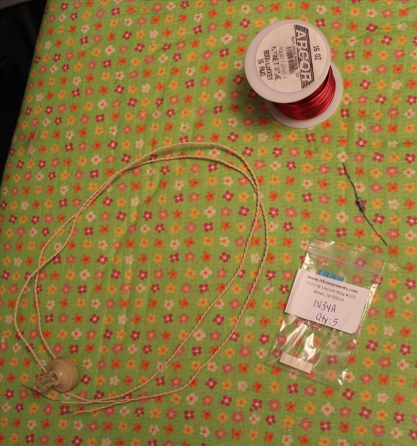
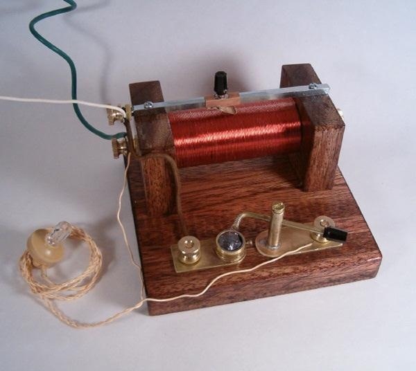
Well, that's a hard question to answer, because each type of wire has plusses and minuses. Generally you'll be dealing with two different types when it comes to crystal radios, insulated wire and magnet wire. For all intents and purposes on this project, insulated wire and magnet wire are the same thing. It doesn't matter which you use, though you can see in the picture below that I used magnet wire.
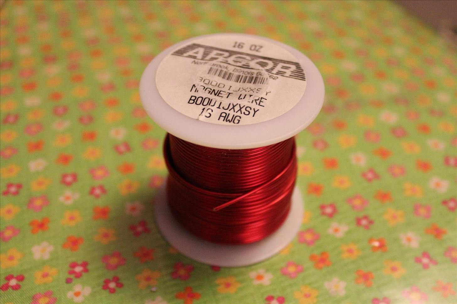
I picked magnet wire for a variety of reasons, but what was most important to me was that it looked more "steampunk". Plastic insulation is pretty modern-looking.
You're going to need to pick a wire gauge, and that will affect your tuning ability. I went with a 16 gauge for mine, but I recommend slightly smaller, as that may be easier to work with. So maybe go with an 18 or 20 gauge, but it's largely a matter of whether you prefer to work with a larger or smaller wire. We can adjust the tuning ability later, based on what gauge of wire you go with.
Magnet wire is really easy to find, and I ordered this one from Amazon.
We'll talk about what exactly to do with this wire later on.
Crystal / Diode
When I first set out to make a Steampunk crystal radio set, I thought to myself, "Yes! I will find a real crystal for my radio, and it will be super authentic and awesome-looking!" That enthusiasm died out pretty quickly, unfortunately, as I came to learn exactly what was entailed in using a real crystal.
The crystals you can use for a crystal radio are pretty limited, and it's not like you can just hook it up to a piece of quartz. Most of the crystals that are useful for a radio aren't ones that look particularly pretty, such as galena, which is a crystal form of lead.
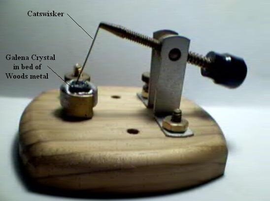
Second, tuning them is a gigantic pain in the rear. A crystal radio that uses a real crystal is called a "cat's whisker" set, because of the way that the wire dangles over the crystal. Essentially, you need to constantly hand-tune them while you're listening, or else you'll lose the signal. It's terrible.
So despite my earnest desire for authenticity, I had to compromise for the sake of not pulling my hair out and just use a modern diode. "Modern" is of course a matter of perspective, as the design of the modern diode hasn't changed significantly since 1930. While I could potentially have used a vacuum-tube diode, they're much harder to come by and still slightly past the Steampunk era. I may continue to look for one, though.
Anyway, here are the diodes I got:
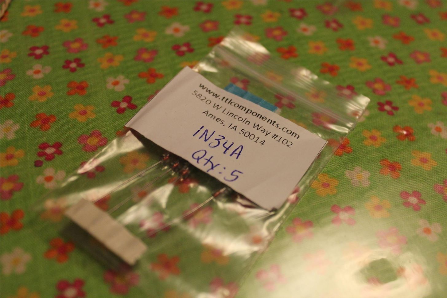
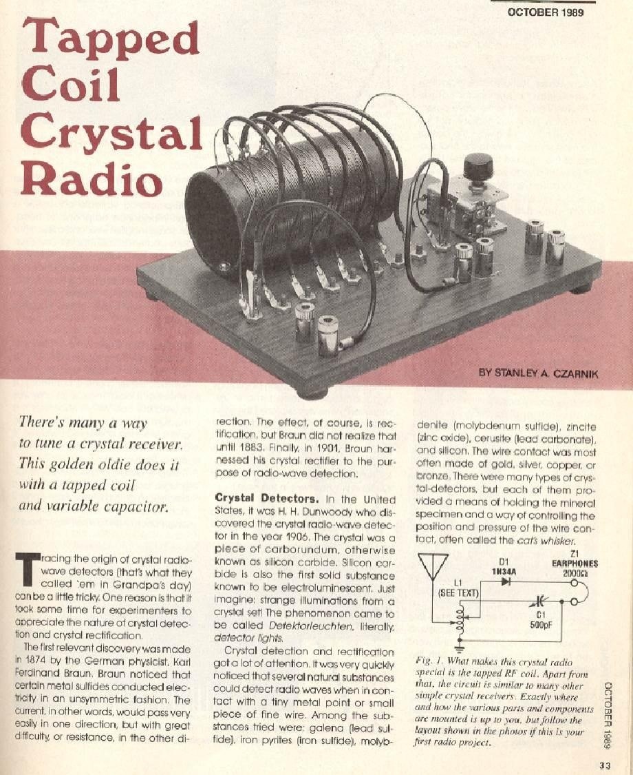
As you can see from the picture, these diodes are type 1N34A, which suffice just fine for a crystal radio.
Here's what they look like:
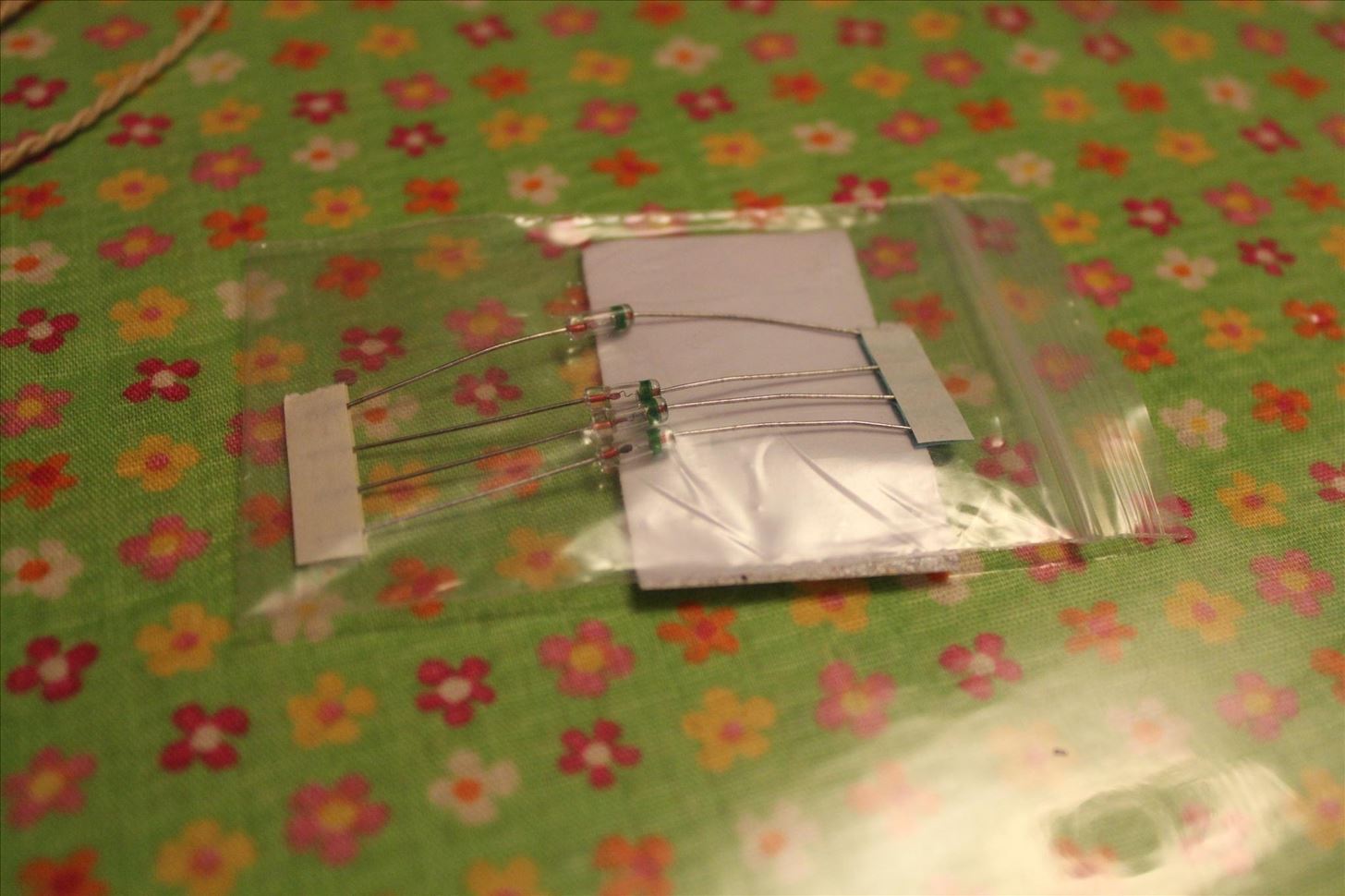
You can actually see, if you zoom in really close in the above picture, that modern diodes are essentially just fixed-whiskers. That is, it's a cat's whisker design, but it's fixed so it can't move.
So, what does a diode (or crystal) do? Why do you need one?
Well, that's a hard thing to explain. What a diode does is transfer a signal in one direction, but not the other, but that probably doesn't mean anything to you at this point.
When you have a circuit, the signal will flow anywhere it can, even backwards. If your signal is flowing both forwards and backwards, you're going to get a giant mishmash of signals if you try to listen to it. They'll cancel themselves out, and do all kinds of things, making it unlistenable. In order to fix that problem, you use a diode to filter your signal on the circuit. That way, you only receive one version of the signal at your earpiece.
If you want to think of it like our water analogy from earlier, think of a circuit as a pool. The water is everywhere in the pool at once, just like the electricity in a circuit. If you throw a stone in the pool, the ripples will flow outward, and if you had a way to measure the waves at the edge of the pool, you would get an unimpeded signal from the waves you made. Now, imagine if you threw two stones in the water at the same time, at opposite ends of the pool. The ripples will meet in the middle and cancel themselves out, making the whole pool kind of wavy, but destroying the purity of either signal. The normal state of a circuit is like the two-stone model, but adding a diode turns it into a one-stone model, allowing a pure signal to be measured at the end.
Speaking of the end....
The Earpiece
This is where your signal ends up, once you've collected it from the antenna and then filtered it with a diode.
In order to actually hear the signal, you need a special type of earphone; the ones you have sitting around your house just won't do. That's because modern headphones are designed to use power, far more power than you can pick up with a reasonably-sized antenna.
Since you have very, very little power coming down your line, you're going to need an extremely sensitive earphone that will react to the tiny vibrations in your circuit. This is called a "high impedance" earphone, or a "ceramic" earphone.
Unfortunately, only one type of high impedance earphone is still being made in the entire world, and it's terribly ugly. There are a variety of places you can buy them from, but I did some research and discovered that they all come from the same factory in the UK. Even more unfortunately, they're crap. The quality is just plain awful, because some just flatly won't work and other die in short order. And what's more, the manufacturer knows it, and refuses to do anything about it. Nice, right? However, if you want to buy a new high impedance earphone, you're stuck because they're the only sellers.
This is what it looks like:
It comes with a normal 3.5 mm jack at the end of it, but for a crystal radio, you'll want to cut that off and expose the two wires at the end. It's only one earpiece, but you need two wires in order to complete the circuit properly. We'll get into that a little more specifically below.
Resistor (Optional)
A resistor is something that lets you manage the amount of power you have on a circuit. Without getting into technical things like current and resistance, it basically lets a certain amount of power through it, so that anything attached to the circuit doesn't get overwhelmed. With a basic crystal radio, you may not need a resistor. However, if your antenna is long enough, you may pick up enough power to blow your diode, which you don't want to happen.
So if you intend to string a long antenna, you may want to include a resistor. This is the one that I used:
It's a 47k resistor, which is... well, rather complicated to explain without getting really technical. To be as simple as I can get, this resistor provides 47,000 Ohms of resistance to the circuit. Resistance helps control the current of the electricity. This is the shallow end of a very, very deep pool, so I think I'll just leave it at that.
What you need to know for this project is that if you're going to have a long antenna, you should include a 47k resistor. They're available for sale through pretty much any electronics store, and you can even order them on Amazon or Ebay.
Making a Coil
Now that you know what the various parts are, it's time to start making a radio!
The first step is to make yourself a coil. Coils are exceptionally easy to make. All you have to do is get something that's non-conductive (plastic, wood, cardboard, etc.) and wrap some wire around it. You want to leave the insulation on, which in the case of regular wire will be plastic, but in the case of magnet wire will be enamel. It will also work better the tighter the coil is, but it will still work with a loose coil.
Ideally, your coil form will be something that's between 4-6 inches in diameter, and hollow. The less material there is between the wires, the stronger the magnetic field they generate will be. The form doesn't even need to be round... A square or rectangle one will work just fine. In fact, for my first crystal radio, I used an empty cardboard box:
Bask in the glory of how ugly that radio is. But you know what? It worked. I could pick up signals, and it was just fine.
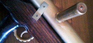
Now, I used a few things that you don't really need for a bare-bones set. First, I had a spare piece of wood lying around that I used as a base. You don't really need that. Second, I had some little metal clips that I used for ease of assembly, but you don't need those, either. Lastly, I had a little alligator clip, but that's not necessary either. The alligator clip may make life a little easier for you, though.
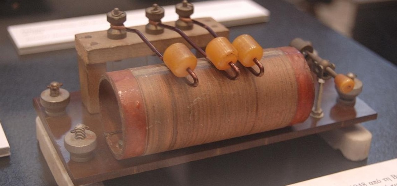
Anyway, what you want to do is wrap your wire around your coil form. Every three turns, make what they call a "tap". Taps are those little loops of wire you see in the picture above. You just take some extra slack and turn your wire into a loop. Do that once every three turns, and do a total of about 40 turns. That means you should end up with 13 taps.
The reason we're doing this is that our coil is effectively a homemade variable resistor. Variable resistors are also known as potentiometers, and they're the device you use in all sorts of things like volume knobs, dimmer switches, and the like. In this case, we're going to use that variable resistor to tune our radio by artificially lengthening and shortening our magnetic field. So, make sure you remove the insulation from your taps. If you have plastic insulation, you'll need a knife to do this, but if you have magnet wire, some sandpaper will work just fine.
Don't forget to leave some slack at the beginning and the end, because you'll need to connect those ends to other things.
Turning a Coil into a Radio
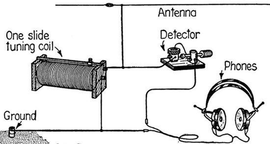
Now that you have a coil with some taps, the rest of the radio is just a matter of connecting your coil to your other parts.
The top of your coil connects to your antenna. Just a simple copper-to-copper connection will suffice for all of these, too... No need to solder if you don't want to. You can simply twist the ends together and tape them, if you don't know how to solder. Just make sure that there's a solid connection, because if any of your wires are loose or don't fully touch each other, you won't get a signal.
So, like I said, the top of your coil connects to your antenna, and the bottom connects to your ground. Having a ground is very important for getting a good signal, though I understand that a good ground may be difficult for people who live in apartments, or in the city.
A ground is exactly what it sounds like: ground. Ideally, what you do is pound a metal rod a few feet into the dirt, and then connect the bottom of your coil to it. Barring that, you can connect your ground wire to some copper water pipes, or any other metal pipes that run into the ground. In other words, you want a way for your circuit to dissipate excess electricity.
Strictly speaking, a ground isn't necessary. Neither is an antenna. Your coil can function as an antenna in its own right, though without an extra antenna and a ground, be prepared to have an extremely faint signal. My current set is portable, so it has a small antenna and no ground, but I've taken some steps to make it a little louder. I'll go over those steps in the next installment of this series, but for now, either stick with an antenna and ground, or forgo them entirely for a weak signal.
From the end of the coil that you're connecting to your ground, you want to run a wire to your earpiece. Or, to half of your earpiece. Connecting an extra wire is easy, just scrape off some of the insulation and wrap one wire around the other. That wire will connect directly to one of the two leads on your earpiece.
This forms the outgoing wire, so that your signal can travel through your earpiece out into the ground.
Next, you're going to connect your diode to the other lead on your earpiece. You can either connect it directly, or via a length of wire. Whatever you prefer.
Lastly, connect the other end of your diode to a length of wire. If you have an alligator clip, attach that to the far end of the wire that's attached to your diode. Otherwise, no worries... Just make sure you remove the insulation from the end of that wire.
That's all there is to it! Now all you do is attach the diode-wire to the various taps on your coil until you hear something.
If you have a good-sized antenna, remember to add your resistor. The resistor will be connected to both leads of your earpiece.
Wasn't that easy? Once you've made the coil, there are really only six connections you have to worry about, and I'll list them here for you:
- Top of coil to antenna
- Bottom of coil to ground
- Ground wire to earpiece
- Earpiece to diode
- Diode to Coil taps (via wire)
- Resistor to earpieces
And now you have a working radio! Attach your diode-wire to the various taps until you find a station!
Troubleshooting
Okay, so, maybe your radio isn't working right off. Crystal radios are such incredibly simple things that there are only a few limited things that could be wrong. I'll try to cover them here.
- Turn your diode around. Your diode may be pointing the wrong direction.
- It's possible that your earpiece is crap, and doesn't work. Put the earpiece in your ear, and hold the two leads with one in each hand. Brush the leads against each other. If you hear a "click" when the leads touch, your earpiece is working. If you don't hear a faint click, your earpiece is broken. Sorry!
- Check to make sure that all of your connections are solid, and that you've removed the insulation at any place where two wires are supposed to connect.
- That's it. Really. A crystal radio is so simple that there are really only three possible things that could be wrong with it.
I hope you've enjoyed this crystal radio tutorial! There are a lot of other tutorials out there, but none of them really explained the theory and concepts behind the radio as much as I wanted them to, which is why I incorporated that stuff into my guide.
Radios can get a whole lot more complicated from here, but there are still ways to add functionality without having to dive off the deep end. In my next article in this series, I'll talk about antenna designs, variable capacitors, and more, so remember to keep checking Steampunk R&D!
Images not taken by me are from WikiMedia Commons, 1632, Makezine, University of Oregon, CrystalRadio.net, and Science Buddies
Just updated your iPhone? You'll find new emoji, enhanced security, podcast transcripts, Apple Cash virtual numbers, and other useful features. There are even new additions hidden within Safari. Find out what's new and changed on your iPhone with the iOS 17.4 update.


8 Comments
I've built several of these radios over the years.
You can get some good steampunk headsets that are actually from the 1920's through the 1950's from Scott's headphones. I've had lots of dealings with him and he knows how to ship vintage phones without damaging them.
Most crystal radios have a faint signal from stations that are 20 or 30 miles away maximum. However, if you have the right parts, a good antenna and ground it is possible to hear stations 100 miles away and farther! Amazing when you consider that there is no power other than the tiny millivolts coming through the air.
This circuit is the one that is like the first radios people used when KDKA made the first commercial radio broadcast on November 2, 1920.
It's like the ones soldiers used in WWII in foxholes. They used a razor blade and a pencil lead instead of a diode or crystal as a detector. The razor blades work pretty well, but not quite as good as the 1N34 diode in this circuit.
If you add a variable capacitor in parallel with the coil, taps are not necessary. Also, you will increase your chances of getting distant stations. If you already have a radio like this, the taps help a little.
I suggest using American made 1000 to 3000 ohm headphones from the 1920's through the 1940's for distant stations. My Cannon Alnico phones are around 2000 ohms and I've heard 14 stations that are beyond 100 miles over the course of 3 years. Most of them 200 or 300 miles.
Wonderful steampunk device and thanks for sharing how to build it.
Question, my science class is going to make a radio.
I have magnetic wire and we are making a coil about 5-6 inches long. I have the diode that you suggested. However I've read that old telephone ear pieces will work for the headset. I haven't complete the project because I just received my diodes but do you think the telephone ear pieces will work?i hoping my class can assemble everything on Monday and have some success but I fear that the earpiece will let them down after reading your article. By the way, thanks for the examples of how this worked. It made it easy to explain to my class and they at least understand the very basic idea behind how this radio works.
what is the difference between using Variable resistors and Variable capacitor for tuning ?
A coil and a capacitor are needed to make a resonant circuit that can tune a particular frequency. Using a variable capacitor or variable inductor or both are needed to tune different stations. Variable resistors are used for volume control, which for a crystal radio, is usually not a problem that needs solving.
The simplest crystal sets, as the one described here didn't have capacitors. They still have a tuned circuit. There is capacitance between the windings of the coil, between the antenna and the earth, etc...
You can still see that kind of tuned circuit used today in multiband antennas such as are used for ham radios and external cellphone antennas. There is a coil in the middle of the antenna with the windings perfectly spaced. This acts a a filter so that higher frequencies see only the bottom section of the antenna but lower frequencies see the whole thing.
That coil with it's taps makes a variable inductor not a variable resistor. A comprehensive explanation of exactly what an inductor is would probably be beyond the scope of the article but it's really nothing like a resistor. You might say that it's function is to store energy in the form of magnetism.
_When is the second instalment coming out?
Share Your Thoughts